Altimeter Datalogger
Transmitter Pictures, PCB & Schematic
The general aim of this project was to find a relatively cheap and reliable altitude remote datalogging system for a model rocket.
The system that I came up with is outlined below along with photographs. At the bottom you can find the complete circuit schematics for the transmitter and receiver, along with the corresponding PICAXE code for the two parts.
Sensor
I decided to go for the altitude sensor approach, largely because it’s cheaper than using an accelerometer. And whilst it required more time to get it working as it should and getting a useable signal from it, that was half the challenge. The sensor I picked was the Motorola MPX4115A.
Signal Conditioning
This sensor is used for pressures between 0 – 115 kPa. Bearing in mind mean atmospheric pressure at sea level is 101kPa, and drops to about 84kPa at around 5000 feet, we need to narrow the range down considerably. I chose 5000feet as the maximum for this project, as it gives me a reasonable range (not that a rocket is ever going to reach 5000feet) whilst giving me a resolution of about 5 feet. A differential amplifier using the MAX494 quad rail-to-rail op-amp was used for this.
Processing
The signal, after conditioning, is fed into a PICAXE 18X microcontroller which reads the analogue signal into a 10bit ADC. The value is then transmitted back to the receiver station over a 433mHz RF link.
In addition, the 18X does other things:
· After every single reading, it checks to see if this reading is the new peak altitude (ADC value lower than previous – as voltage falls with increasing altitude). It logs the peak altitude in its internal EEPROM.
· It records a “zero” value at the beginning of each flight. When transferred to a computer, this “zero” value can be taken away from subsequent readings. As such, it eliminates the problem of changing atmospheric pressure between flights.
· One in every 10 or 20 (depending on log time) readings is logged to internal EEPROM as well as being sent over RF. This is so that, in the event of the receiver failing, huge amounts of interference, etc, some data from the flight is still available from the onboard device.
Transmission
A cheap (£10) 433mHz pair of RF modules were used for this. There’s not much to say – they work perfectly sending serial data directly through them. I found N1200 was the fastest baud I could use whilst getting nearly perfect signal over around 80-90m range. At N2400 baud, the range decreased to around 50m – the time saving of doubling the baud was not worth the loss in range.
Note: I used a full wavelength whip antenna at the time for this project. I later discovered 5/8 wavelength whip is far better. If this is too long, a 1/4 wavelength whip will still give better results than a full wavelength one.
Receiver
The receiver is not very interesting – at least not as much as the transmitter. When switched on, it waits for a “start logging” command from the transmitter. Once received, it waits for the beginning of the data stream. It takes each reading, makes sure it is 1023 or below (because it is only 10bit ADC, any higher values MUST be interference). There is no parity or CRC, as this technique of “1023 or less” catches 99% of errors, after extensive testing! The data is then logged to a 24LC256 EEPROM. When required, the data can be read back to a computer; either in plain text, or in SelmaDAQ mode. This puts the data directly into Microsoft Excel so a graph can be plotted, and other calculations performed on the raw results.
Power
The transmitter is simply powered by two 3V lithium coin cells, providing 6V to the MAX883 regulator. When switched on, the PICAXE takes control of the “shutdown” pin on the regulator, keeping it high. This keeps the regulator running and supplying power to the PICAXE and the rest of the components. When finished logging (or its current task) the PICAXE sends the leg low, shutting off the circuit completely. As such, should the rocket land on a roof, or in a tree, the batteries will not run themselves down. Standby current is around 7 microamps. Idle current is 10mA, and transmitting data (ie. Peak power usage) is 17mA. As such, around 6 hours TOTAL run time can be expected from the two coin cells.
Internal Data
After a flight, the transmitter can be powered up along with the receiver, and a button on the transmitter sends its internal data to the receiver (ie. “zero” value, peak reading and one in every 10/20 readings), which the receiver logs to a second 24LC256. This data is returned to the computer in both plain text and SelmaDAQ modes.
Results
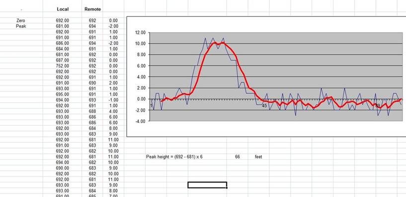
This screenshot shows data from a full rocket launch. The pressure was set at 2.5Bar. By taking away the “peak” value from the “zero” value and multiplying by the resolution in feet, the peak height can be determined (66 feet in this flight). The flight itself can be clearly discerned from the graph.
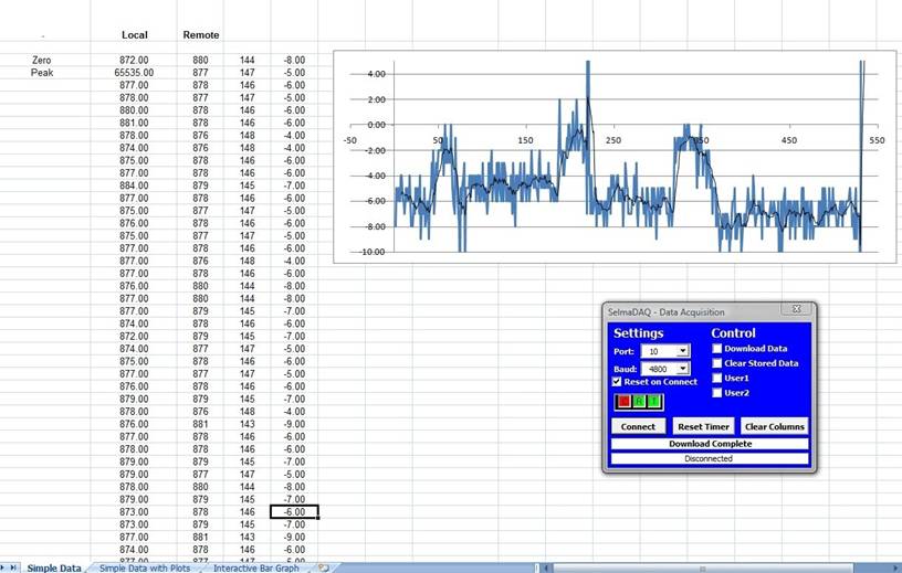
This screenshot was the data from a 35 second “flight”. I actually threw the module into the air three times during these 35 seconds. Looking at the graph, you can see this clearly. Please ignore the spike at the very end.
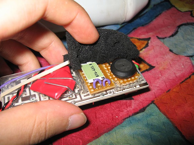
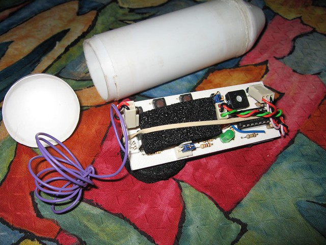
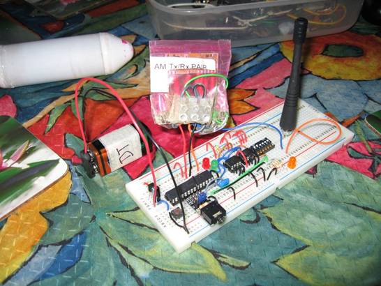
Here you can see the two coin cells on the left, held together with electrical tape and a paper clip. In the middle, the RF transmitter, with the purple antenna lead. On the right, the MPX4115A pressure sensor.
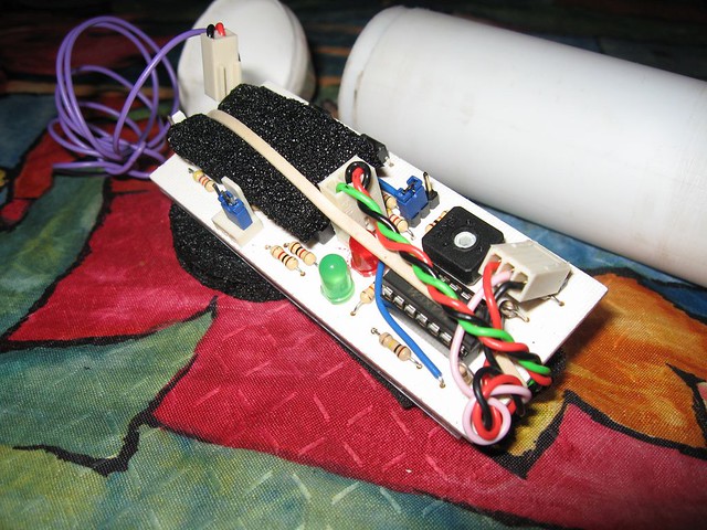
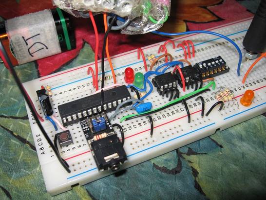
The top side of the PCB, showing the two status LEDs. The pot is the calibration for the differential amplifier. Beneath it is the MAX494. Under the black foam lies the MAX883 regulator along with the PICAXE 18X. On the far left, the coil of purple wire is the 61.3cm antenna (one 433.92mHz wavelength).
The blue jumper in the middle of the board, next to the pot and LEDs, is “automatic mode”. In manual mode, you must press a button to take the “zero” reading, test the connection, then again to start logging. In automatic mode, a “zero” reading is taken, the system enters “testing connection” mode for 30 seconds. After this, the system logs for the programmed amount of time (I usually set this at 45 seconds). After this, it shuts down.
The three buttons on the board are located in the top left of the PCB in this picture. From left to right:
1) Slightly hidden under the power lead – POWER. Pressing this allows power to the MAX883 and the circuit powers up, after which the PICAXE takes control of the power.
2) Test connection/start log/stop log. In automatic mode, can be used to stop manually logging.
3) Transmit internal data – returns the 18X’s internal data to the receiver via RF.
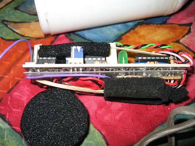
The module. The PICAXE and regulator can be seen on the topside under the foam. The three pin header at the front, with the blue jumper, is a connection for the PICAXE download socket.

The completed module sealed and ready for flight – one end is permanently sealed; the other is masking taped shut once the system is running and ready to fly.
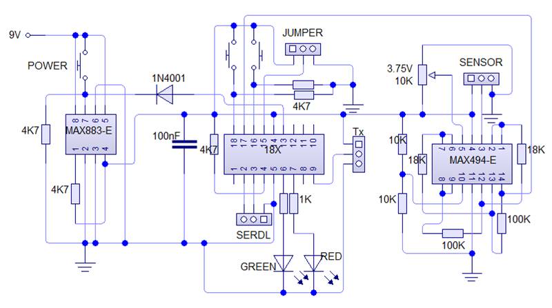
Full transmitter circuit schematic is shown here.
Sensor port (from left to right) - +5V, Signal, GND
Transmitter port (top to bottom) - +5V, Signal, GND
Serial Download Port (from left to right) - Serial In, Serial Out, GND (Remember that required download resistors are not included in this schematic)
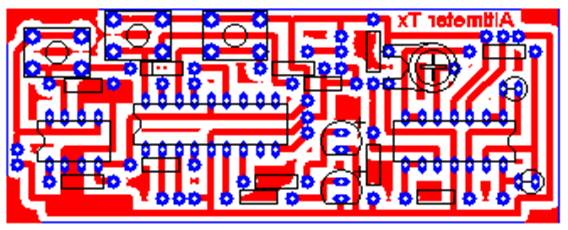
Design for the transmitter PCB.
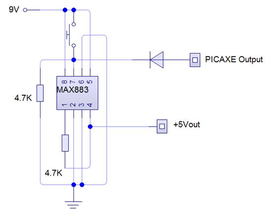
Schematic for allowing the PICAXE to control its own power via the MAX883 5V LDO regulator.
[top]
The receiver circuit on breadboard. A standard 433mHz antenna is in use.
The PICAXE 28X1 IC can be seen here, along with the dual 24LC256 EEPROMs and a dip switch bank.
The circuitry on the far left of the board is the 5V regulator circuit.
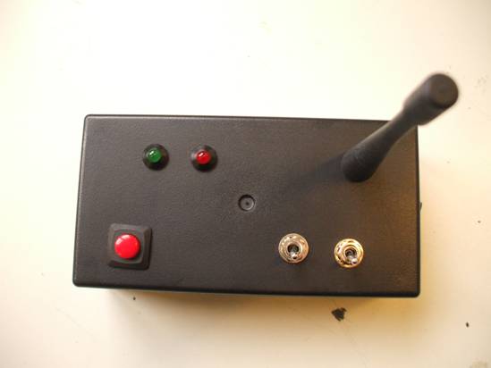
The final receiver built into a standard plastic box. The antenna is removable for storage in order to prevent damage.
The two status LEDs can be seen in the top left, with the red PICAXE reset button in the bottom left.
The two mode switches are located in the bottom right. The first sets LOG or PLAYBACK modes, the second determines PLAINTEXT or SELMADAQ playback.
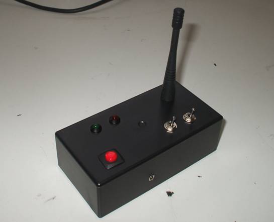
The serial download port can be seen on the side of the box here.
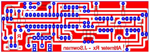
PCB Design for the receiver circuit.
[top]
PICAXE Code for the Altitude Logger
Transmitter
For a PICAXE 18X
Download Zipped Code
Receiver
For a PICAXE 28X1
Download Zipped Code
[top]
Jon Sowman 2008