Ultrasound Distance Ranger
This system was designed to be pointed at something, and it then tell you how far away it was. This type of device is often used by surveyors: newer ones use lasers. However these are very complex and well beyond the scope of my electronics abilities!
As such, ultrasound is the traditional method of finding distance. The concept behind it is extremely simple: one can determine the speed of sound in air (~340m/s) and by timing the gap between a pulse of sound being sent, and it being received after being reflected, one can determine the distance travelled there and back, using s=vt. Divide this by two, and voila!
Transmitter
The transmitter is the simplest part of the system: it is required to send a given-length pulse of ultrasound when instructed.
![]()
The transmitter system is a simple 555 timer circuit. The output on pin 3 is
attached to a transistor. When the base goes high, current is allowed to flow
from the +9V power supply, through the 560Ω protective resistor and then
through the 40kHz ultrasonic transducer, to ground.
Pin 4 (ping) is a reset and whilst kept low, the timer is disabled. A
microcontroller or logic of some sort needs to be attached to this pin to send
a precise 200uS high pulse. During this 200uS, the 555 timer will emit pulses
at 40kHz, which drives the transducer.
Along pin 3 there is a point marked frequency test. Connecting a frequency
calibration device or an oscilloscope between this point and ground will allow
calibrating the 555 frequency to exactly 40kHz, by means of the 10kΩ
variable resistor.
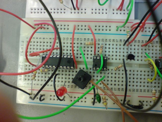
Receiver
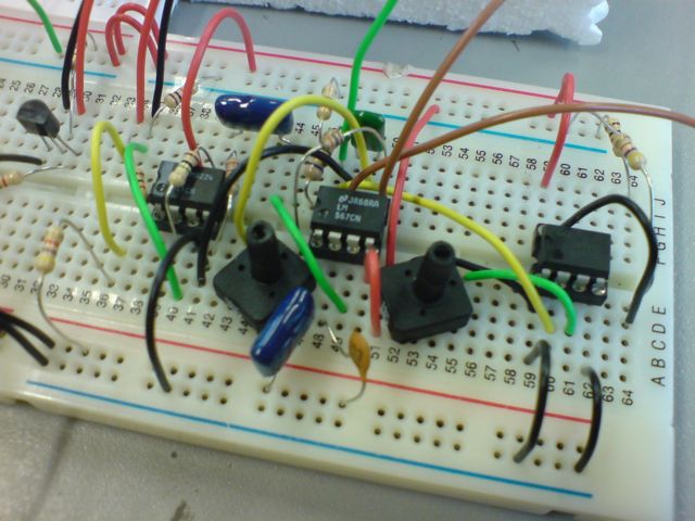
This circuit diagram shows the receiving part of the ultrasound system. It
is split into two sections, each doing a part of the
processing of echoes, before eventually passing the signal on to a
microcontroller or other logic system for measurement of time
lag via the “echo” output.
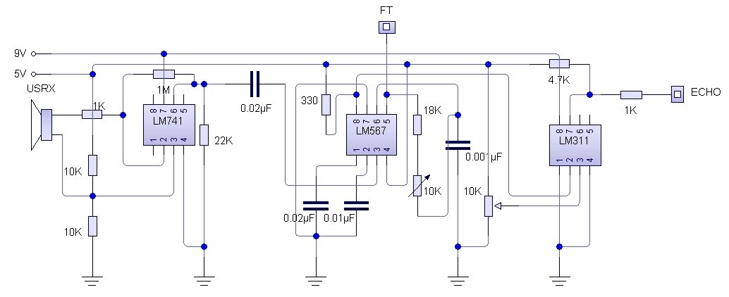
Amplification
When the 40kHz ultrasonic transducer picks up the signal, it is extremely weak.
Before any processing can be completed on the signal, it must be amplified.
This is done by means of a LM741 – an operational amplifier. This IC has
a gain of 1000, ie. It multiplies the difference in voltage between the two
inputs (pin 2 and 3) by 1000. Therefore the small voltage created by the
ultrasonic transducer is amplified by 1000 so that the tone decoder can pick up
the signal.
Tone Decoding
The transducer will pick up most sounds within a fairly wide range. To make
sure the system only picks up the ultrasound signal that was transmitted, we
need to lock the receiver onto a certain frequency. This is done by the use of
the LM567CN Phase Locked Loop Tone Decoder IC. The chip has a 555 timer built
into it which is used to set a reference frequency. The “frequency
test” pin can be connected to an oscilloscope to set the reference
frequency to 40kHz. After this, when a signal at 40kHz is applied to the input
(pin 3), the voltage at pin 8 will drop LOW. When any other frequency signal,
or no signal, is applied to the input pin, the voltage at the output pin will
stay high.
False Triggering
The returning signal will be very dirty and so a system needs to be put in
place to make sure that the timing circuit “sees” the very first
echo, even if it is very weak. Without any amplification or re-processing, this
first signal may not be of a high enough voltage for the timer circuit to
“see” it as high, and it will miss it. Therefore an LM311 voltage
comparator will be attached to the output of the LM567CN Tone Decoder. A
reference voltage can then be set, so if that a signal is above a set
threshold, instead of outputting a weak signal to the timing circuits, the
receiver will output a full 7V high signal. In this way, it can be ensured that
the timing circuit does not miss the first returning signal, even if it is very
weak.
Control System
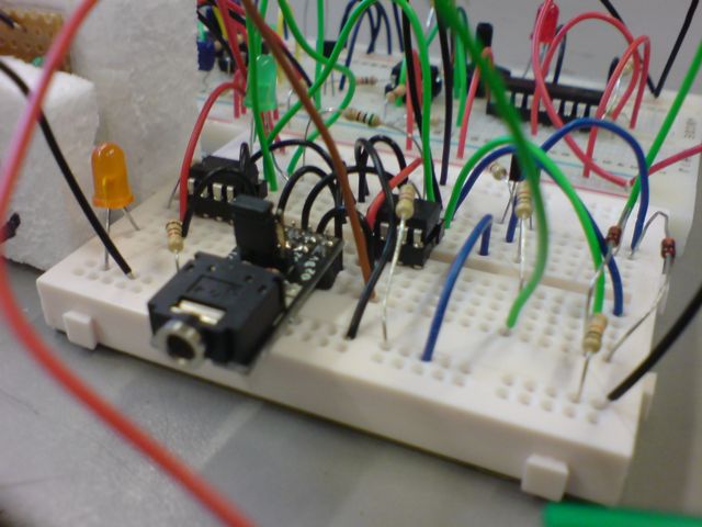
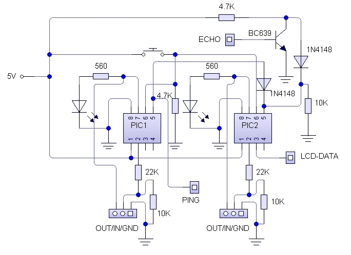
As this device is designed to be a distance sensor, there needs to be a
control system in place. This system will:
1) Send an accurately timed pulse to the 555 timer. The timer will then
emit the 40kHz pulse for this amount of time.
2) Once the pulse emission has finished, the control system will begin
timing.
3) On the first echo received, the system will stop the timing.
4) From length of recorded time, the system should be able to determine
the distance in real world units (for example centimetres).
The PICAXE ICs are suitable for this, in that they can send accurately timed
pulses and perform the mathematical calculations which will be needed to work
out the real world distance from the pulse length.
The disadvantage is that the PICAXE chips have no accurate or reliable method
to measure a length of time. The only way to do this is via the „pulsin‟
command. Even running overclocked to 8mHz, a PICAXE will not “see”
a pin go HIGH or LOW quick enough for the timing to be accurate.
Therefore attaching the “echo” line directly to a PICAXE is not
possible. So an alternative method needs to be found using the „pulsin‟
method. This command measures the length of a pulse on a certain pin. This can
start on a LOW->HIGH transition and finish on a HIGH->LOW transition, or
vice versa.
The ping (output to the 555 timer) line is low by default, and will go high for
a set amount of time, to send the 40kHz pulse. The echo line is high by
default, and will go low when an echo is received. For use of the "pulsin‟
command, the two lines need to be combined. However, this cannot be done, as a
default high and a default low will just create a short circuit. Because of
this, the echo line will need to be inverted by the use of a logic system. In
addition, both lines will need diodes to prevent damage by current from one
line flowing up the other line.
When a signal is received, the echo line drops low. The echo line is then
pulled high through the resistor. This LOW->HIGH transition is used to end
the timing pulse, having been started by the HIGH->LOW transition at the end
of the “ping” pulse. The amount of elapsed time is then
recorded as a value in the second PICAXE chip. At the stock speed of 4MHz, the
time is measured in 10uS units.
Overclocking
As mentioned earlier, the PICAXE ICs can be “overclocked” to run at
twice their default speed (to 8MHz from 4MHz). Some can be overclocked to
16MHz, but these do not include the PICAXE-08M chips that I will be
using. The reason for overclocking the chip is as follows: each command
the PICAXE processor completes takes a set amount of time. Unlike a PICmicro or
similar PIC device programmed in machine code, the BASIC coding used for the
PICAXE chips is far less efficient.
If we take the following code as an example:
do while pin1=0 X
Y loop
goto setValue
This code loops around in a circle until pin 1 goes high. When it does, it
jumps to the function called “setValue”. If the pin goes high at
point X, it will take less time for the PICAXE to move its processing cursor to
the function “setValue” than if the pin goes high at point Y. The
time difference is extremely small, but when working with ultrasound pulses
that are in themselves only microseconds long,
this tiny inaccuracy in “seeing” a pin change state can cause a
considerable inaccuracy in end result.
This is where overclocking comes in. By doubling the PICAXEs clock speed, the
processing speed is doubled. Therefore the “check” for a high pin
will happen twice as many times per unit time as when running at default speed.
The upshot of which is that the accuracy is doubled.
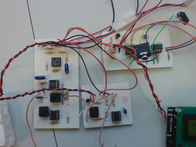
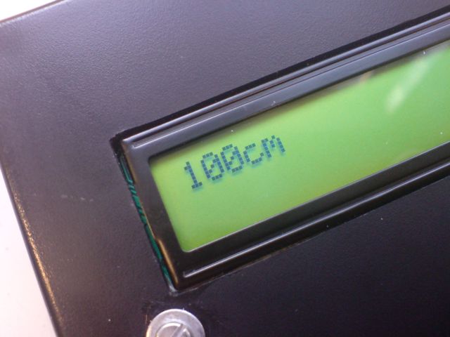
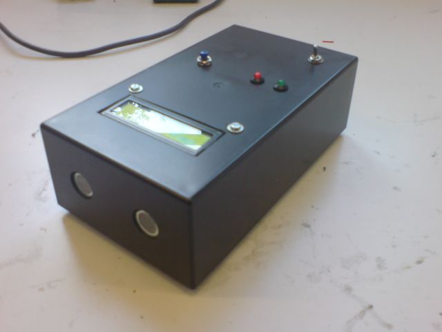
Testing & Pictures

PICAXE Code
Please click here to download a ZIP file containing the *.bas PICAXE programs for the two PICAXE-08M chips on the control board. The one with "pic2" in the name is the one for the timing PIC (the one attached to the LCD screen). The one with "pic1" is, therefore, the one for the transmitter control PIC.